The use of heat accumulators for the heating system allows optimizing the combustion of solid fuels in boilers. In simple words, if there is a buffer tank - a heat accumulator, the homeowner does not need to visit the boiler room often, and the firewood will burn up in the optimal mode. But for this, the capacity must be correctly selected, and then docked with heating equipment, which will certainly cause difficulties for an ignorant person. Therefore, it is worthwhile to understand in detail what a heat accumulator for a solid fuel boiler is, how to choose it and connect it to the heating of a private house.
What is buffer capacity?
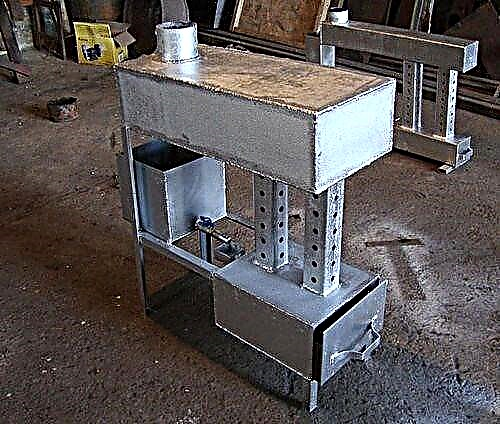
In fact, a heat accumulator designed for a heating system is an ordinary metal tank of estimated capacity, covered with a heat-insulating layer. In the simplest factory-made models, there are only nozzles for connecting a coolant, and sleeves for installing thermometers. Thermometers are already integrated in buffer tanks, while the most expensive products are equipped with heat exchangers in the form of coils. The device of such a heat accumulator is shown in the figure:

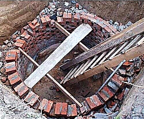
As you can see, the design of the buffer tank is not particularly difficult, therefore different craftsmen - craftsmen adapted to do it with their own hands, as described in a separate topic.
The purpose of the coils is to heat water to provide domestic hot water and to connect alternative sources of thermal energy - solar collectors. It is clear that this function is in demand only under favorable weather conditions in the region of residence. In general, the buffer tank for the heating boiler is designed to solve such problems:
- Creation of conditions for the operation of a TT-boiler with maximum efficiency and minimum emissions.
- Comfortable operation of the heat generator, when you do not need to throw firewood into the furnace every 4-6 hours, including night time.
- Heating and supplying drinking water of quality to 1-2 consumers (option).

Most manufacturers of solid fuel heating equipment indicate in the attached documentation that it is highly advisable to connect a heat accumulator to the TT boiler. The reason is this: the unit achieves the greatest efficiency with an operating mode close to maximum. And since the excess heat generated must be placed somewhere before being fed into the heating system, a buffer tank with water will be needed.
Without a thermal accumulator, we try to "strangle" the thermal unit in every possible way, limiting the supply of combustion air. Not only does this reduce its efficiency to 40% (like a potbelly stove), but it also causes the release of toxic carbon monoxide into the atmosphere. Because of this, some European countries have banned the burning of wood and coal in heating boilers without a buffer tank.
With more rare visits to the furnace room, everything is clear: the heat accumulated in the tank will be spent on heating the house for a long time, provided that its volume is correctly calculated. In addition, when a solid fuel boiler is working in conjunction with a heat accumulator, the probability of overheating and boiling of water in the unit jacket is reduced to almost zero.
In addition to interacting with wood heat generators, heat accumulators can also be used with electric boilers. This makes sense when the electricity consumed at night is considered at a rate that is 2-3 times lower than usual. For the period of time while this tariff is in effect, the electrical installation will be able to fully “charge” the heat accumulator, and it will give this energy to heat the house during the day.
With this option, the results of the previous calculation of the power of the electric boiler will have to be doubled so that its heat transfer is enough to heat the house and load the tank at a night rate.
Buffer capacity calculation
The main criterion by which a buffer tank for a solid fuel boiler is selected is its volume, determined by calculation. Its value depends on such factors:
- thermal load on the heating system of a private house;
- heating boiler power;
- expected duration of operation without the help of a heat source.
Before calculating the capacity of the heat accumulator, it is necessary to clarify all of the points listed, starting with the average thermal power that the system consumes during the winter period. The maximum power should not be taken for calculation, this will lead to an increase in the size of the tank, and therefore to an increase in the cost of the product. It is better to endure inconvenience and load the firebox several days a year more often than pay a crazy price for a large heat accumulator, which will be used irrationally. And he will take up too much space.
Expert opinion. To provide thermal energy to a house with an area of 200 m², a buffer tank containing 1 ton of coolant is enough, and this is a volume of 1 m³. The statement is true for the middle zone of the Russian Federation, in the more southern or northern regions the alignment will be different.
The normal operation of the heating system with a heat accumulator is impossible when the heat source has a small power margin. In this case, it will never be possible to fully “charge” the battery, since the heat generator must simultaneously heat the house and load the tank. Remember that the selection of a solid fuel boiler for piping with a heat accumulator involves a double supply of thermal power.

It is proposed to study the calculation algorithm using an example of a house with an area of 200 m² with a boiler idle time of 8 hours. It is assumed that the water in the tank heats up to 90 ° C, and during heating operation cools down to 40 ° C. To heat such an area in the coldest time, 20 kW of heat will be required, and its average consumption will be about 10 kW / h. This means that the battery must accumulate 10 kW / h x 8 h = 80 kW of energy. Further, the calculation of the volume of the heat accumulator for a solid fuel boiler is carried out through the formula for the heat capacity of water:
m = Q / 1.163 x Δt, where:
- Q is the estimated amount of thermal energy that must be accumulated, W;
- m is the mass of water in the tank, kg;
- Δt - the difference between the initial and final temperatures of the coolant in the tank is equal to 90 - 40 = 50 ° C;
- 163 W / kg ° C or 4.187 kJ / kg ° C is the specific heat of water.
For this example, the mass of water in the heat accumulator will be:
m = 80,000 / 1.163 x 50 = 1375 kg or 1.4 m³.
As you can see, as a result of the calculations, the sizes of the buffer capacity come out more than the expert recommends. The reason is simple: inaccurate source data were taken for the calculation. In practice, especially when the house is well insulated, the average heat consumption for an area of 200 m² will be less than 10 kW / h. Hence the conclusion: in order to correctly calculate the dimensions of the heat accumulator for a solid fuel boiler, it is necessary to use more accurate initial data on heat consumption.
For reference. There is also an enlarged calculation method, according to which for every kW of thermal power of the boiler there is 25 l of the volume of the heat accumulator.
Heat storage selection
The remaining criteria for choosing the capacity are not so important and mainly relate to different options. One of them is a built-in coil heating water for household needs. It may be useful if there is no other means of heating, but for high costs in the DHW network, this method is definitely not suitable. In addition, the heat exchanger will take away part of the “charge” of the heat accumulator, reducing the battery life.
A useful option is a heating element integrated in the upper part of the tank, capable of maintaining the temperature of the coolant at a certain level.Thanks to electric heating, the system does not defrost in the event of an accident and can even heat the house for some time after the battery has "discharged" and the boiler has not yet been started.

The second coil for connecting the solar system is useful only in the southern regions, where solar activity will allow you to load the heat accumulator. But what you should pay attention to when choosing is the working pressure of the tank. It should be borne in mind that most solid fuel boilers are designed for a jacket pressure of up to 3 Bar, which means that the buffer tank must easily withstand the same amount.
Wiring diagrams
There are many ways to tie a solid fuel boiler with a heat accumulator and heating system. But they are all derivatives of the basic circuit shown below. With its help, it is easy to figure out how these units work in pairs, and then mount everything yourself.

An important point. The actual capacity of the boiler circuit circulation pump should be slightly higher than that of the heating circuit pump unit. Observance of this condition will allow the flows inside the heat accumulator to move in the right direction (shown in the diagram by white arrows).
In fact, the mains pump will be more powerful than the boiler, and that's why. The resistance of the network of pipelines and radiators is higher than 3-5 m pipes from a solid fuel boiler to a heat accumulator. The unit needs higher power and pressure in order to overcome this resistance. Therefore, a weaker boiler circuit pump can provide a higher flow rate, you just need to correctly configure both units. There are 2 options for resolving the issue:
- When using 3-speed pumps, you can adjust their performance by switching speeds.
- Put at the input of the return from the system to the buffer tank a balancing valve, with which to adjust.
Simultaneous heating of heating devices and layer-by-layer loading of the heat accumulator is possible when the flows inside the tank move horizontally with a slight predominance from the solid fuel boiler. The question arises - how to check this? There arises an answer: on both inputs of the return to the tank you need to put thermometers (as in the diagram) and perform the adjustment by switching the speeds of the pumps or by rotating the balancing valve. An important condition: the three-way valve of the heating network must be fully opened manually.
Alternative scheme
This scheme of tying the buffer tank and solid fuel boiler was proposed by one of the participants in the popular forum. Its peculiarity lies in the fact that when the power is turned off, the operability of the circuit is maintained, although it is necessary to pay for it with increased diameters of steel pipes. The figure below shows the connection of the heat accumulator to a closed heating system, but during installation it is better to make it open, as the author himself says.

Briefly, the essence is this: thanks to the T-shaped input from the top of the tank, the radiators are simultaneously heated and the thermally-accumulator made by oneself is “charged”. The boiler circuit pump is controlled by an overhead sensor on the supply line, including the unit, when it reaches a temperature of 60 ° C. The circulation in the network depends on the room thermostat with which the network pump is connected.
Note. The proposed strapping scheme was verified by its creator on their own experience. All details of its installation and operation are described by the author on the forum.
Conclusion
The fact that the heat accumulator improves the operating conditions of a conventional solid fuel boiler cannot be denied. The latter burns fuel with maximum efficiency, and after heating the number of trips to the boiler room is reduced to a minimum. Another thing is that this pleasure is not cheap, because of which the lion's share of batteries working in private homes are home-made.