Most of the electrical circuits are developed and used in low-current systems. The main purpose of this kind of circuit is the transformation of incoming signals according to the laid down algorithm of actions.
For galvanic isolation of low-voltage and higher voltage ratings, an intermediate relay is used. Due to their small size and reliability, these devices are widely distributed in various fields.
Appointment and functions of the device
This type of switch is an auxiliary object in the electrical circuit. The versatility of the samples allows their use in automated, protective and control circuits.
It is used in cases when there is a need for synchronous closure or opening of several autonomous electrical circuits, in other words - the multiplication of live channels.

Connection diagram of the emergency button of the car: by means of one contact line of the electromagnetic relay, the switch can be turned off, and the second one can play an audible warning in the alarm unit
The contactor can also be used as a regulator of a more powerful relay, due to which a high voltage circuit is switched.
Take, for example, this situation: there is a need to supply current to the circuit breaker inductance, where the maximum instantaneous value of the electro-driving force when turned on is 63 A. However, it is not possible to perform such a task using one electromagnetic apparatus.
Therefore, it is initially necessary to supply power to the core coil of a separation device using its own connections, to turn on a contactor with a higher power, which will be entrusted with the task of switching a larger electric power.
Also, the part can be used to create an artificial delay in the action of the protection relay or, as they say, to form a time delay.
The structural structure of the device
Electromagnetic devices are connected to an electrical circuit that monitors or adjusts products that are connected to a power unit for conversion. Starting can be carried out by the influence of various kinds of factors: power supply, light energy, hydrostatic or gas pressure.

The constructive device of the electromagnetic relay: 1 - spring; 2 - movable anchor; 3 - ferromagnetic rod (core); 4 - coil; 5 - base; 6 - one or more fixed contacts; 7 - executive body
According to standards, the simplest contact device is coordinated by three main areas: perceiving, intermediate and executive. Each of them is represented by an individual mechanism responsible for certain actions in the switching system.
The primary, the so-called sensitive, element responds to the input parameter and transforms it into the physical quantity required for the contactor to function.
Such a perceiving mechanism is embodied in an electromagnetic coil with a core - indicated on the diagram by number 4. Depending on the network, either alternating or direct voltage can be connected to it.
The intermediate link begins a comparative analysis of the converted value with the embedded sample. As soon as the set value is reached, the node transmits a signal of the sensitive mechanism to the actuator. This section consists of counter springs (1) and dampers.

Soothing elements in the contactor are used to eliminate vibrations of the moving segments, and in the time relay - to provide the necessary time interval
In the production part, through the switching lines (6) located on the housing above the block, the effect on the slave line is reproduced and the contacts close.
The principle of operation of the contactor
The algorithm of operation of this type of relay involves the use of electrodynamic forces created in a ferromagnet during the passage of electricity along a spiral of turns of an insulated coil wire.

Based on the technical features of the switch and the number of contact links placed in it, the anchor either closes or opens them
The initial location of the L-shaped plate (anchor) is fixed by a spring. By applying a current to the magnet, the anchor, with the commutation contact located on it, overcomes the forces of the spring and reaches for the magnetized field.
When moving the shank, located on the plane of contact, catches the lower contact circuit, moving it down. If the coil stops supplying electricity, the spring pulls the yoke back and the device takes its original form.
Let's look at an example of how an electromagnetic type relay works in a car.
If it is connected to a three-phase asynchronous motor, the following actions will be reproduced:
- Start - turn on the alarm.
- Trigger starter.
- The closure of the last pair of contacts as a result is the start of the engine mechanism.
In addition, it is the relay that is responsible for turning off the motor when the reverse breaks. This eliminates the problem of abrupt engine shutdown.

To recognize the type of electromagnetic contactor in production, marking values are used, consisting of a set of letters and numbers printed on the device
It is also important to know that an electromagnetic relay can be equipped with several groups of control contacts. The number of the latter completely depends on the purpose of a particular model of the device.
Varieties of intermediate switches
Intermediate contactors unload main actuators. Otherwise, the extinguishing conditions will become more stringent, which will make production unprofitable, for example, of such powerful sources as thermal power plants.
Used inclusion methods
The classification of electromagnetic switches is carried out according to the main features and characteristics, namely:
- by the method of inclusion;
- design features - the number and type of windings, as well as the number, condition and power of contact lines;
- principle of action;
- by the response time and return to the initial position.
Based on the purpose, the contactors are made with a voltage or current winding, or in two varieties at the same time. Two unified methods of their connection are distinguished.

The electromagnetic device must be turned on not only with the standard mode of operation of the power source, but also with emergency indicators, working to reduce the current to 40%
The first type of connection is serial. The device is connected in series in sections of the windings of other devices and operates on current flowing along the circuit of this circuit.
The next one is a shunt. It is included in the rated voltage indicators of the operating current source.
Features of the design of the device
The device features suggest samples with one turn of a voltage or current winding (RP-23, RP-252), two (RP-11) and infrequently with three.
DC relays (RP-23) are produced at such nominal voltage values: 12, 24, 48, 110 and 220 V, alternating current (RP-24) - 127, 220 and 380 V.

RP-23 device: an electromagnet with a winding, an anchor with a shank, fixed and movable contacts, a spring, an adjustment plate. The contactor is mounted on the base and closed by a casing
Switches types RP-23 and RP-24 are designed to operate on galvanic current and have 5 contact lines, which can be used in different combinations. The differences between them in their device.
The second type of device is equipped with a built-in mechanical trip indicator. Their power consumption at a base voltage of 6 watts. The RP-25 and RP-26 series operate exclusively on alternating current and are arranged in the same way as previous devices.
An additional element is a short-circuited coil on a core with a coil, designed to eliminate vibrations of the moving part of the mechanism. Their energy consumption is the same - 10 watts.
Recently, CJSC CHEAZ (plant for the production of electrical appliances in Cheboksary), instead of the above modifications, is reorienting to modernized models. These are the switches RP16-1 (galvanic current) and RP16-7 (alternating current), equipped with two disconnecting and four closing contact groups.

The new generation distributor RP16-7 is aimed at including protection and automation in selective power circuits for switching electrical loads
Two- and three-winding peripheral devices are usually used in several cases.
Consider what tasks they solve and what type of device this will require:
- If you need to activate the operating mode from current and hold from voltage, for example, the RP-232 series with a single-turn working winding.
- If action of the device against voltage and abstention from electricity is necessary - RP-233 on two holding current turns.
In the same way, instead of the above contactors, ChEAZ is introducing new models RP-16-2 - RP16-4 and RP17-1 - RP17-5.
The principle of operation of the switches
Contact devices are used in the communications and automation segment. Based on the principle of operation, they are divided into neutral and polarized (pulsed) species.
The main difference between them is that in the former, the armature displacement is not subject to the polarity of the control signal, in the latter, on the contrary, they are directly dependent on the direction of motion of the charged particles in the winding.
Neutral switches have the simplest device, consisting of two systems: contact and magnetic. In the contact group there are two fixed and one generalized movable contact. The magnetic assembly consists of an anchor, an electromagnet and a yoke.

Diagram of a neutral electromagnetic relay: c) with an armature retracted into the coil. If the control signal is at the maximum distance - the armature is removed from the core - one pair of contacts is closed, and the other is open
Additionally, electromagnetic relays are divided according to the nature of the movement of the armature: angular (float) and retractable. To reduce the resistive forces of the magnetic air channel between the movable plate and the core. The latter is equipped with a pole piece.
Such relay circuits are used in control systems of production machines and machines. RES-6 is one of the representatives of low-current contactors of the neutral class. The device may take the form of a two-position or one-stable device. Its rated operating voltage is 80-300 V, switching current is 0.1-3 A-V.
The impulse category is composed of the same systems. However, the magnetic section of the pulse relays is additionally equipped with two rods with a winding, as well as a contact rod and a permanent magnet that creates a polarizing flow.
Due to this type of supply, the tendency of the electromagnetic force acting on the armature changes based on the direction of the power flow in the coil.

Design of the polarized relay ИМШ1-0,3: coil, permanent magnet with pole extensions and plate, stand, spring, communication lines. The increase in the reaction speed of the device is achieved due to the material of the core - sheet steel
IMSh1-0.3 contactors are widely used as a traveling relay mechanism in pulsed protective (RE) galvanic current circuits. IMVSh-110 is used in alternating current circuits. Technically, it consists of a diode bridge that converts variable forces into a constant value.
Response and Return Time
The response time of the intermediate mechanism (t attraction) is the period from the moment the command arrives at the trigger until the start of the increase in output parameters. This value is completely subordinate to the design features of the relay, its connection scheme and input signal.
Shutdown time (t release) - the interval from the signal to turn off until the output parameter reaches the lowest value.

Scheme of the deceleration block when the relay RP18 is triggered. The deceleration process is ensured by semiconductor circuits, to the output of which the relay windings are connected
The type of relay under consideration has high performance requirements.
Depending on the response time interval, the devices are classified as follows:
- high-speed - deceleration time on attraction and shutdown to 0.03 s (for example, REP37-13, RP 17-4M);
- normal - 0.15–0.20 s (RE series);
- slow - 1.0-1.5 s (NMM4-250, NMM4-500);
- temporary - more than 1.5 s (RP18-2-RP18-5).
On the market, such modifications are represented by various manufacturers. Therefore, depending on the brand, the design of the relay may vary slightly. However, using markings on the device, you can accurately determine the parameters of the product.
What will the labeling say?
In the marking of contactors, a complete set of data on the purpose and design features, including information on the climatic version, is indicated.

Decryption of the TKE520DG model: a device with a winding exposure of up to 30 V, and contacts - up to 5 A, there are two make contacts, the device design provides for a long-term operation mode, is hermetically sealed
Let us consider in detail the structure of the symbol on the example of PE41 (Н) (*) (*) (*) (*) (*) / (*) (*) (*) (*) 5:
- REP - electromagnetic relay intermediate.
- 37 (N) - development number.
- (*) - designation of the type of current in the circuit of the including winding: 1 - direct current; 2 - alternating current.
- (*) - type of deceleration: 1 - decelerated when turned on; 2 - slowed down when turned off.
- (*) - value based on the number of windings;
- (*) (*) - numerical value of the closing and opening contacts;
- (*) (*) - voltage or current of power winding: constant (D) and alternating (A);
- (*) (*) - designation of the electric power of the holding windings;
- (*) - the type and technology of connecting the rear conductor lines: 1 - with lamellas for soldering; 2 - mounting with screw fixing; 3 - fastening with terminals to the split block.
- (*) 5 - climate design and placement category according to GOST: UH - moderately cold; In - all-climatic.
When choosing the necessary model of the switching device, not only its electrical parameters are taken into account, but also the environment in which it will work.

The selection of the contactor is based on the required characteristics: power supply (V), power consumption (W), switching current (A), contact groups, operating time (s), sizes
Despite the envisaged high quality of the switch, the main drawback lies in the contact system. It is assumed that a pure connected group can only be in sealed vacuum conditions. If the main negative factor acts - contact with air - an oxide film begins to form on them.
Nuances of connection and adjustment
After installing the intermediate mechanism, it must be connected to the electrical circuit. For this, the contacts of the coil will be involved, as well as additional connecting elements. Typically, a device has several contact pairs: NO - normally open and normally closed (NC).

The distribution of groups in the presented wiring diagram: 10-11 - normally-closed contacts; 11-12 - normally open; contacts 1 (phase) - 3 (zero) - relay supply voltage
In the first position, the complete deprivation of the signal to the coil is assumed.Since there is no polarity in it, the internal connection of the contact group can be carried out in a chaotic manner.
To connect the overview mechanism, consider the schematic instructions. The estimated voltage in the coil can be: 12, 24 or 220 V.

Wiring diagram of the device without connecting to the network. Its installation is carried out in control and automation circuits. Location - between the main executor and the source of the task
We will analyze the regulation of the electronic starter using the example of the most common RP-23 model.
The process consists of the following steps:
- Checking the start-up and return voltages with the supply of a galvanic current source to the coil, we carry out unsharp regulation.
- At the moment of the anchor attraction, the moving unit of the system must have a joint stroke of 0.1-1.5 mm. By the method of bending the shank on the L-shaped plate, we carry out the correction procedure.
- Between the active and inactive contact, the gap level is set within the range of 1.5-2.5 mm. The deflection is set by pressing the square of the fixed contacts and the upper stop of the movable system.
- With the final location of the armature (short circuit), the failure of inactive contacts will be 0.3-0.4 mm.
- In the middle of the plane, the movable and fixed contacts must match. Correction is made by moving the plate and the guide bracket.
Using the same method, the RP-25 relay parameter settings are also reproduced, however, the gap between the core coil and the armature in the drawn state is eliminated.
The principle of operation of the electromagnetic relay, where applicable, is also considered the main indicators of reliability of devices. More details in the video:
Having chosen the necessary model of the device, we proceed to its connection and configuration. The main nuances are described in the plot presented:
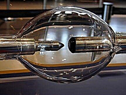
Technological developments in the construction of intermediate relays have always been aimed at reducing weight and dimensions, as well as increasing the degree of reliability and ease of installation of devices. As a result, small contactors were placed in an airtight casing filled with compressed oxygen or with the addition of helium.
Due to this, the internal elements have a longer operational period, uninterruptedly fulfilling all the embedded commands.
Tell us about how to choose an intermediate disconnecting device for your home electrical network. Share your own selection criteria. Please write comments in the block below, post a photo on the topic of the article, ask questions.